Shader Breakdown - LCD Display
🏗️ 正在翻译中。在此之前请先阅读英文的版本。
This post is the breakdown of LCD display shader. Source code for Unity URP is provided.
Github
Source Code
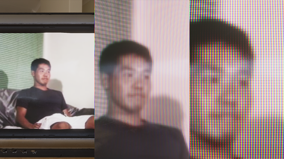
After reading this shader tutorial by Alan Zucconi, I decided to make my own version of LCD display shader. This effect itself is quiet simple, when viewing from distance, the LCD display act identical as a standard emissive material. But once you move close enough to the display, you can see the individual pixels of the LCD screen. What different from the original tutorial is, I use derivative in fragment shader to determine when to reveal the pixel structure of the display therefore the shader can adapt to all kinds of texture with different resolution.
Pixelize Display Content
When you magnify the texture, you will notice that the texture become blurrer. That’s because the texture is using Bilinear filtering. When sampling one point on the texture, four nearest pixels value were grabbed and interpolated base on the distance to the sampling position. However on the actual display, each display pixel can only emits exactly one color. So it is only reasonable that the display content texture should use Point filtering to keep the pixel grid when magnify, but Point filtering also cause some sampling artifacts since the sampling point can’t always lands exactly on the position of one texture pixel. Is there a way to keep using Bilinear filtering and making the texture pixelize when close-up?
And yes there is. We can manipulate the uv coordinate to trick the texture filtering. Using floor() returning the biggest integer that smaller than the texture coordinate, we can snap to the position of the nearest pixel to sampling point.
float2 pixelMaskUV = uv * _BaseMap_TexelSize.zw;
float2 pixelizedUV = floor(pixelMaskUV) + float2(0.5, 0.5);
pixelizedUV /= _BaseMap_TexelSize.zw;
You can also use ceil() or round(), they are functionally same here. Now we just need to know when to use the normal uv coordinate and when to use the manipulated uv coordinate. Hold on a second, we gonna figure it out in following section.
LCD Display Pixel Geometry
We need a texture that represents the geometric arrangement of the display pixel that revealed when close-up. A quick google search of “LCD pixel” will do the trick for you, or you can draw one by yourself like I do. Note that that are some displays out there using none standard layout, like Pentile style display, but we won’t get into these and only stick with the normal stripe-style RGB pixel layout for the sake of simplicity of this tutorial.
We want to know the dimensions of the texture we using as the display content, and use it to scale the uv coordinate so that the pixel tile on each pixel of the texture. In Unity, you can call TextureName_TexelSize and the thoughtful engine will automatically set up the right value for you.
float2 pixelMaskUV = uv * _BaseMap_TexelSize.zw;
Then we simply multiply the LCD pixel texture and the color sampled from the display content texture. You might immediately notice that the display become fainter than before. The reason why is we multiplied the color with the pixel texture, however each color channel’s subpixel only occupied less than 1/3 of the pixel grid, so we lost over 2/3 of the luminance. We can compensate the lost brightness by multiply the color with a multiplier. You can find out the right value of your own pixel texture in Photoshop’s histogram view. Take my texture as example, the histogram view tells the average value of red, green, blue is around 63, hence the multipier should be 255 \(\div\) 63 \(\approx\) 4.
half4 pixelMaskColor = SAMPLE_TEXTURE2D(_PixelMask, sampler_PixelMask, pixelMaskUV);
pixelMaskColor *= _PixelLuma;
Also, the texture seems to has some weird color shift while viewing from certain distance. That is cause by some undesired artifacts of the automatic generated texture mipmap. It is very clear in the figure down below. The 5th level of the mipmap is completely turns into another color that we don’t really want. We need a way to figure out the right texture mipmap level.
Each mipmap level generated by Unity. Take a look on Mip 5, you can see why it is causing trouble.
Why don’t use the “Fadeout Mip Maps” option?
Fadeout Mip Maps in texture import setting can fadeout the selected mipmap levels to gray. In fact I do used Fadeout Mip Maps and it can effectively eliminate the color shift artifact. However the gray color it fadeout to isn’t necessary the gray you want, for example my pixel texture should average to 25% gray but it turns out to be a very arbitrary 53% gray, means the color value won’t be identical with the standard emissive material after applied luminace multiplier. That being said we still need to figure out the actual mipmap level used in fragment shader and do some operations it.
Manually Compute Mipmap Level
Let’s start addressing the elephant in the room here —— where is the right distance that we start revealing the pixel structure on the LCD display with different resolution? The natural idea is, it depends on the pixel real estate on screen. When a LCD pixel is occupying over a certain amount of screen pixel, we reveal it. And that happens to be how we calculate which texture mipmap level to use in fragment shader!
Let’s take a look at how texture lod level is calculated. The OpenGL specification actually give us a detail explanation of how this is done. In the chapter 3.9.11 we have the following equation:
\[ \lambda(x, y) = \log_2{\big(\rho(x, y)\big)} \]
where \(\lambda\) is the level-of-detail parameter, and \(\rho(x, y)\) is a scale factor such that:
\[ \rho = max \Bigg\{ \sqrt{\Big(\frac{\partial{u}}{\partial{x}}\Big)^{2} + \Big(\frac{\partial{v}}{\partial{x}}\Big)^{2} + \Big(\frac{\partial{w}}{\partial{x}}\Big)^{2}}, \sqrt{\Big(\frac{\partial{u}}{\partial{y}}\Big)^{2} + \Big(\frac{\partial{v}}{\partial{y}}\Big)^{2} + \Big(\frac{\partial{w}}{\partial{y}}\Big)^{2}} \Bigg\} \]
Okay, the partial derivative might looks scary at the first glance. Let’s break it down step by step. The \(\partial{u} / \partial{x}\) indicates the derivative of \(u\) with respect to window \(x\), put it in another word, the change rate of texture coordinate between screen pixel currently evaluating and the adjacent pixel on the right. In GPU, fragment shader never runs individually on one pixel. The smallest unit that execute fragment shader simultaneously is a 2\(\times\)2 grid. So the fragment actually has access to the adjacy pixels’ data. We can use the fragment shader only functions ddx() and ddy() to calculate the derivative value. Assuming the value is monotonic, therefore we have \(\partial{u} / \partial{x} = u_{0} - u_{right}\).
The \(u\),\(v\), as you might expected, is the texture coordinate. Note that this texture coordinate values here isn’t normalized. Take a 512\(\times\)512 texture as example, the texture coordinate of the center of the texture is expected to be (256, 256) instead of (0.5, 0.5). So the scale factor \(\rho\) is the longest display pixel length covered by the screen pixel currently evaluating.
Finally we compute the binary logarithmic of the scale factor to get the lod value. If one screen pixel covered one LCD display pixel, the lod value is 0. If one screen pixel covered two LCD display pixels, then the lod value is 1. Covered four then lod become 2 and so on. That actually make sense since we know that the texture size is halved each mipmap level down! Lastly we can move the square root out of binary logarithmic saving us some instructions, and the equation become:
\[ \lambda(x, y) = 0.5 \times \log_{2}{\Bigg( max \bigg\{ \Big(\frac{\partial{u}}{\partial{x}}\Big)^{2} + \Big(\frac{\partial{v}}{\partial{x}}\Big)^{2}, \Big(\frac{\partial{u}}{\partial{y}}\Big)^{2} + \Big(\frac{\partial{v}}{\partial{y}}\Big)^{2} \bigg\}\Bigg)} \]
Converting into HLSL code.
// The OpenGL Graphics System: A Specification 4.2
//  - chapter 3.9.11, equation 3.21
float2 pixelMaskTexcoord = pixelMaskUV * _PixelMask_TexelSize.zw;

float2 duvdx = ddx(pixelMaskTexcoord);
float2 duvdy = ddy(pixelMaskTexcoord);

float scaleFactor = max(dot(duvdx, duvdx), dot(duvdy, duvdy));
float mipmapLevel = 0.5 * log2(scaleFactor);
Why don’t use
CALCULATE_TEXTURE2D_LOD?There is nothing stopping you using
CALCULATE_TEXTURE2D_LODinstead ofComputeTextureLOD, however, keep in mind that using it in your code will require shader model 5.0 which isn’t always supported in your target platform. Conduct your own research.
Putting Stuff Together
Now we can interpolate between the normal texture and pixelized texture, and reveal the LCD pixel base on texture lod value. The texture lod value needs to be remap to [0, 1] before use to interpolation. In my case, I want to start revealing the pixel structure at mipmap level 4 and fully switch to LCD pixel at mipmap level 3. Feel free to experiment with different values and find the right combination for you.
half pixelization = saturate(Remap01(mipmapLevel, half2(1, 4)));
half pixelremoval = saturate(Remap01(mipmapLevel, half2(3, 4)));

uv = lerp(pixelizedUV, uv, pixelization);
half4 texColor = SAMPLE_TEXTURE2D(_BaseMap, sampler_BaseMap, uv);

pixelMaskColor = lerp(pixelMaskColor, half4(1, 1, 1, 1), pixelremoval);
half3 color = texColor.rgb * pixelMaskColor.rgb;
Make sure the HDR and post processing are enabled and use the ACES tone mapping so that you can see the effect. We also want to use Trilinear filtering for the LCD pixel texture. Trilinear filtering will interpolate between mipmap level on top of Bilinear filtering, effectively remove the abruptly jump between texture lod when zoom in and zoom out with the cost of a small overhead.
Finally, to add some finishing touches, you can implement some glitch effect that I won’t going to in this post. There are all sorts of glitches out there, and the most common one is interlacing artifact caused by the mismatched refresh rate of signal source and display. You don’t have to overexaggerate the effect since modern days displays handle glitches very well. I gonna leave the implementation to you.
Conclusion
That’s it for this small breakdown of LCD display shader, hope you learn something about derivative in fragment shader and texture lod (I certainly do). You can find the full source code on my Github. Also I put the link to the original shader tutorial by Alan Zucconi down below, and a similar article by Austin O’brien that definitely worth reading.
Other Useful Resources
Alan Zucconi
LCD Display Shader Effect
Austin O’brien
Slime Rancher Pixel Display